Geoscan Planner
Preset
Connect CRL modem with the laptop.
Turn on UAV power.
Run application MdmDisp.
The antenna icon and the number of connected UAV’s on the screen’s lower right corner are displayed.

MdmDisp program indicator
3.1 The first turn on, you need to configure connection with UAV.
Run NetTopology:
Click on Search icon.
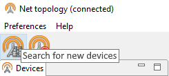
Search icon
The program shows a list of detected modems.
Note
The button is fixable. It should be pressed again to stop searching.
Choose UAV №xxx and click on Add device icon.
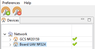
Add device
The program saves the list of added devices.
Just run MdmDisp and make sure that the connection is successful on next time.
You can reconnect the RCL modem by clicking Reconnect in context menu, if UAV is not detected.
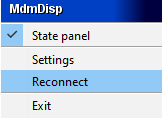
Context menu MdmDisp
Run the program Geoscan Planner.
Enter your login and password.
In context menu Flight select Connect to the UAV – Search… for a searching UAV’s.
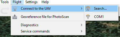
Connect to the UAV
Select type of connection MdmDisp. Set IP-address localhost. In Vehicle list set UAV - Port 6.
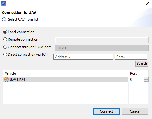
Connect to the UAV
Note
The program saves UAV’s automaticly. Next time click Connect the UAV on the toolbar for reconnect the UAV. The receiver will automatically detect the coordinates and display the UAV location on the map. The telemetry panel (left) and the instrument panel (right) will shown in program window.
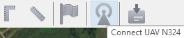
Connect UAV
Flight task creating
Create New project.
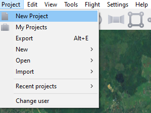
New project creation
Set a project name, shooting parameters, UAV and camera.
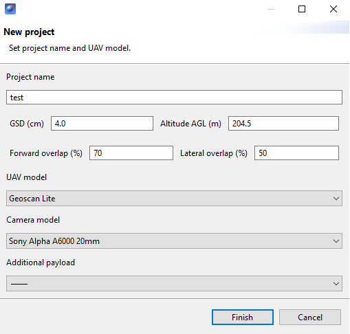
Project parameters
Areal surveying
Areal surveying is an aerial photography of polygons. The operator sets the vertices of the polygon, and the program automatically calculates the route for UAV.
Click on the icon Create areal surveying on the toolbar.
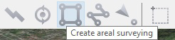
Areal surveying creation
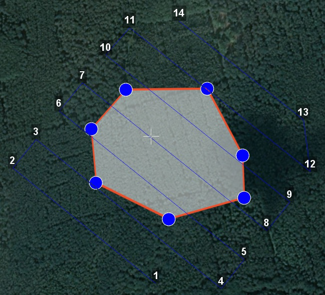
2) By single mouse clicking specify the angular points of the research site. The program automatically calculates the route for bypassing the polygon. It is enough for the operator to create a polygon directly along the boundaries of the investigated area, the program will increase the length of the overfights and their number in accordance with the survey conditions by itself. When creating a route, UAV climb and descent is displayed as the cylinders if the difference in heights of neighboring points is not less than 30 meters.
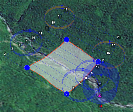
Climb and descent cylinders
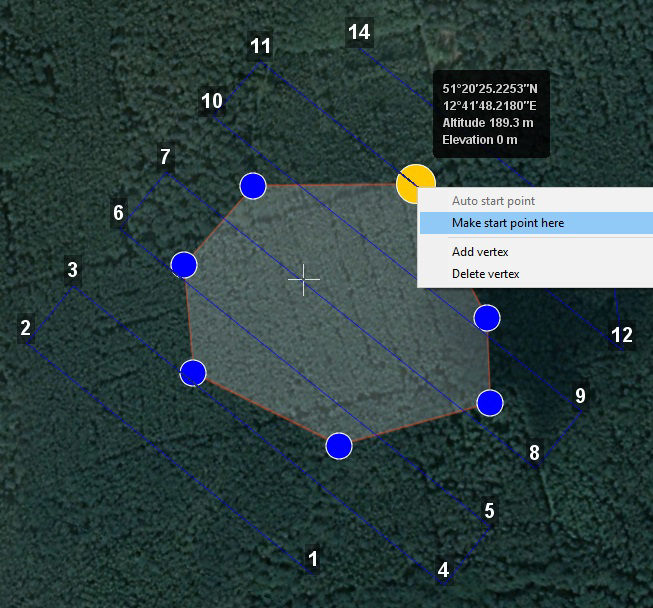
Adding and removing polygon vertices.
You can add vertices to the completed polygon.
Hold the left mouse button and move the middle point of the polygon side.
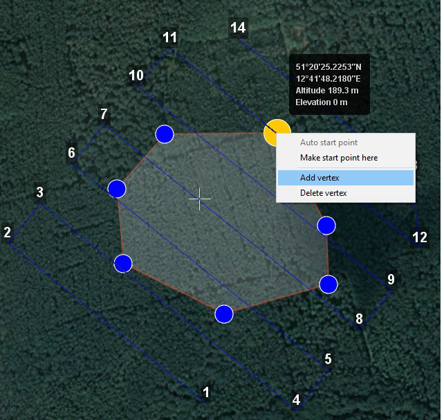
Adding the vertex
The vertex will be created automatically. In a floating window near the vertex will display its coordinates.
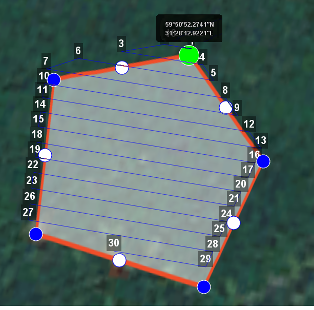
Result of adding a vertex
To remove vertex:
Click right button on vertex.
In menu select Remove vertex.

Remove vertex
Changing the direction of the route lines.
The necessity of optimizing polygon “by direction” occurs quite often, for example, if the force and direction of the wind are unfavorable at the site of work (strong wind along the lines of the overflight above the polygon). To change the type of optimization, right-click on the polygon and select the option Optimization by “direction” in the context menu.
Right-click on the polygon area.
Select Optimization by “direction”.
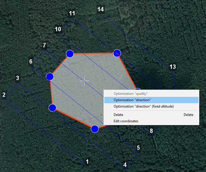
Optimization by direction
One of the vertices of the polygon will be highlighted and a rotation marker will appear on it to set the direction.
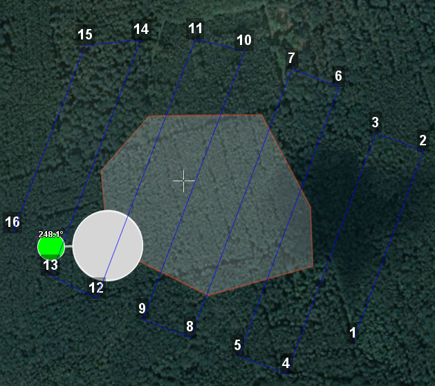
Adjusting the direction of flight
As a Result, there will be a new route to fly around the area in the specified direction.
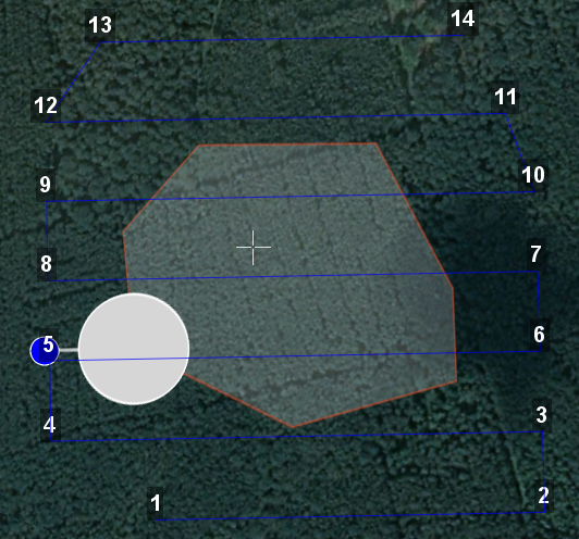
New flight route

Linear surveying
Linear aerial photography is performed in order to survey linear extended objects, such as: rivers, roads, power lines, oil pipelines.
Click on the icon Create linear surveying on the toolbar.
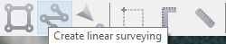
Linear surveying creation
Single-click to specify the route of traversing the extended object by turning points. The program will automatically draw lines of flight.
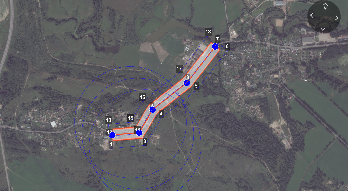
Example of linear surveying
Hop
Fight by pre-set route with a set altitude. It is mainly used for passing above point objects (i.e. high objects) and topographic inequality.
Click on the icon Create hop on the toolbar.
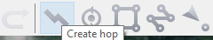
Hop creation
Specify the flight route by single-clicking. To build a hop at different altitudes, select Optimization - Custom altitude in “Properties” window.
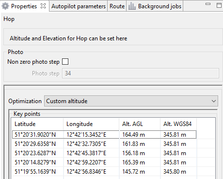
Hop creation
** Non zero photo step** function activates the camera.
You can change the step of photo in meters is specified in the corresponding field. Values of the Alt. AGL column are the differences between the absolute height of the flight task point and the relief below it. Thus, the height of the relief must be taken into account. The absolute heights of the points are also available for editing through the column Alt. WGS84. Besides, height can be changed by visual editing (drag mouse with Shift key pressed).
Hop route between two flight elements is built according to the following rules:
If the flight elements have the same height, then the flight will be performed at the same height.
If the fight elements have different heights, then the flight will be performed at the highest of them.
Attention
If conditions do not allow to reach the height of the second point by a straight trajectory (for example, due to small distance between points, but a large difference in altitude), the aircraft will fly with the maximum allowable pitch by a straight trajectory in order to reach a point by the coordinates, after which it will rise/descend in a spiral.
Waiting point
Waiting point serves to hold the indicated point at the specified altitude during the specified time interval. Also, waiting point allows to measure the direction and force of the wind at a specified altitude.
Click the button Create waiting point on the toolbar.
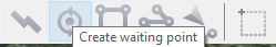
Waiting point creation
Click and specify the point, where a waiting should take place.
In expert mode properties may be changed: setting an altitude of the waiting point, the waiting time and activation of the wind measurement function.
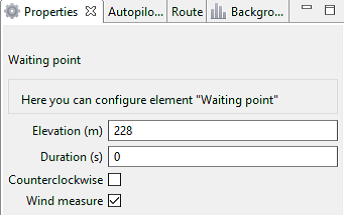
Waiting point options
The UAV will hold the point for the specified time (300 seconds by default) at the specified height, and then go along the planned route.
When ** Wind measure ** is activated, the duration is automatically set to 0. The last point will turn yellow. The UAV flies in a circle, taking into account wind measurements.
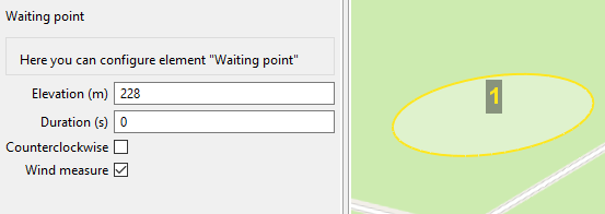
The point of wind measurement
Infinite waiting
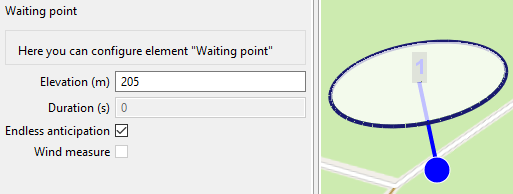
Point of infinite waiting
Attention
It is recommended to set a point of waiting with the wind measurement before each flight element at an altitude of the flight element. Taking into account the wind measurement data, UAV will go smoother along the route.
Landing route
Command Create landing is used to make a landing route.
Building a landing route is an indispensable action at the stage of preparing a flight task.
On arrival at the survey area, determine the wind direction, correct the zone of fight (if necessary) and select the landing site. For landing should be chosen an open space without water bodies, trees and other obstacles. For landing site, choose a open field or meadow without water, trees and other obstacles.
Click on Create landing icon on the toolbar.
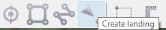
Landing route creation
By single-clicking select the landing point first, and then the point of landing approach.
Program automatically creates the landing route, which consists of 3 points (the middle point is created automatically).
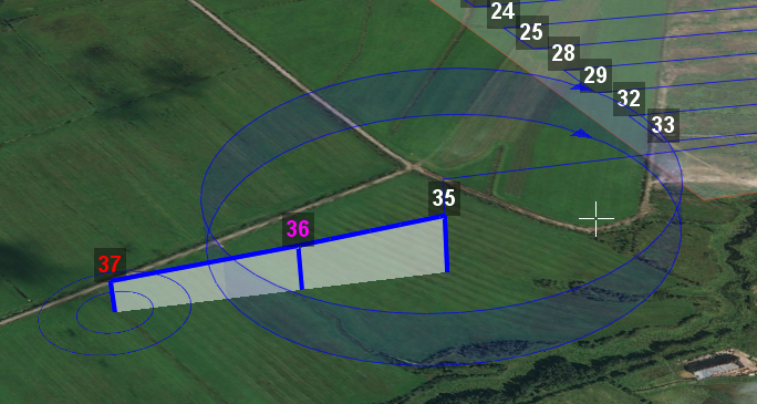
Example of landing
Attention
It is necessary that the landing is being performed against the wind. Otherwise, a hard landing is possible, leading to the aircraft damaging.
Pre-launch preparation
Launch Start preparing Wizard.
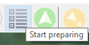
Start preparing Wizard launch
Follow the instructions of the Start preparing Wizard (most tests are runned automatically). Set the radius of the automatic parachute detaching and autonomous flight time (time in flight without the connection between the GCS and UAV). After fight preparation is complete, place UAV on the launcher.
Flight
Click on the icon Start.
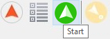
Start
The telemetry panel displays CATAPULT mode.
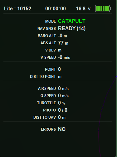
CATAPULT mode
Attention
It is necessary to switch the UAV to a start mode only after placing it on the launcher. It is forbidden to take and move the UAV after switching to CATAPULT mode.
Attention
To cancel the switching to Catapult mode, press the cancel button Cancel. UAV will be switched to the Preparation mode. It will require to go through the flight preparation again.
Turn the safety off and activate the launch device, pulling the launching cord.
UAV will take off.